DEVHEE/ai-robot-hand-with-raspberry-pi
Robot / AI Robot Hand with Raspberry Pi - 2. Electronic Control Research
Robot / AI Robot Hand with Raspberry Pi - 2. Electronic Control Research
Type of Motors
DC Motor
A DC motor is literally an electric motor that uses DC(Direct Current) as a power source. A permanent magnet is placed on the stator, which is a fixed portion of the outside, and is configured using a coil on the rotating body inside. The rotational force is obtained by using the repulsive force between the magnetic field and the magnetic field generated by switching the direction of the current flowing through the rotating body (rotator/electron). The DC motor may operate by inputting power to the (+) and (-) poles, and may change the rotation direction by connecting the poles in reverse. It is used when fast and continuous rotation is required, such as electric vehicles, fans, and RC cars. However, it is difficult to use in devices that rotate by a certain angle or require accurate control, such as robot hands.
Servo Motor
So what came out is Servo Motor. Servo is an abbreviation for Servo Mechanism, and in Japan Industrial Standards (JIS), it is defined as a control system configured to follow arbitrary changes in the target value with the position, orientation, and posture of an object as the amount of control. In addition, Servo is said to be due to the Latin word Servue, which means faithful to its owner. In other words, servo motors represent motors that operate faithfully with the owner's commands, and operation refers to the three elements of position, speed, and acceleration, but can be expressed in two ways: position control and speed control. Position control controls speed to follow the position, and speed control controls instantaneous acceleration to follow. Unlike ordinary motors, servo motors refer to motors designed to quickly and accurately follow command values of frequently changing positions or speeds. The servo motor must have a structure capable of responding to rapid acceleration and braking. Therefore, the thermo motor must satisfy the following two conditions.
- Have great rotational force (torque)
- The moment of inertia of the rotor will be small
As such, servo motors consist of motors, gearboxes, and control circuits, and are widely used in automation production systems, robots, toys, and home appliances as motors that can be accurately controlled through feedback from motors when moving to specific locations or operating at specific values (speed).
Motor Control
PWM(Pulse Width Modulation) Outline
What is PWM?
A method of driving the servo motor is control using PWM. PWM, called pulse width modulation, is a periodic control method that controls the width of a pulse.
Signals include analog and digital signals. Graphs of analog signals are connected in a curved form, such as sinusoidal waves, but graphs of digital signals have only two values, 0 and 1, so the two functions of y=0, y=1 are connected to the time (x) axis.

Analog has countless points connected continuously at the same time as the height changes, while digital signals have only two values of 0 or 1, and do not have intermediate values when changing from 0 to 1 to 0. For example, the light of the LED is indicated by 1, and the non-luminous state is indicated by 0. However, the intensity of light consists of countless values between 0 and 1, and analog signals would be appropriate if these signals had to be controlled. The same applies to the speed control of the motor. Usually, the raspberry pie with a voltage of DC 5V is set to 1 and the non-voltage is set to 0 .
To this end, DA conversion must be made to change the digital signal to an analog signal, and the Digital Analysis Converter (DAC) method and the PWM (Pulse Width Modulation) method can be used. PWM is a kind of eye trick that makes digital signals look analog, not actually analog.
The principle of PWM.
Let's find out the principle of controlling the motor using PWM. Remember that digital signals in motor control can have only two states: 1 when a voltage of 5V is at stake and 0 when not at stake.
For example, suppose that a voltage of DC 5V is applied to a DC motor for 10 seconds and the total number of revolutions is 100. If you walk for 5 seconds, the total number of revolutions is 50 times, and if you walk for 1 second, the total number of revolutions is 10.

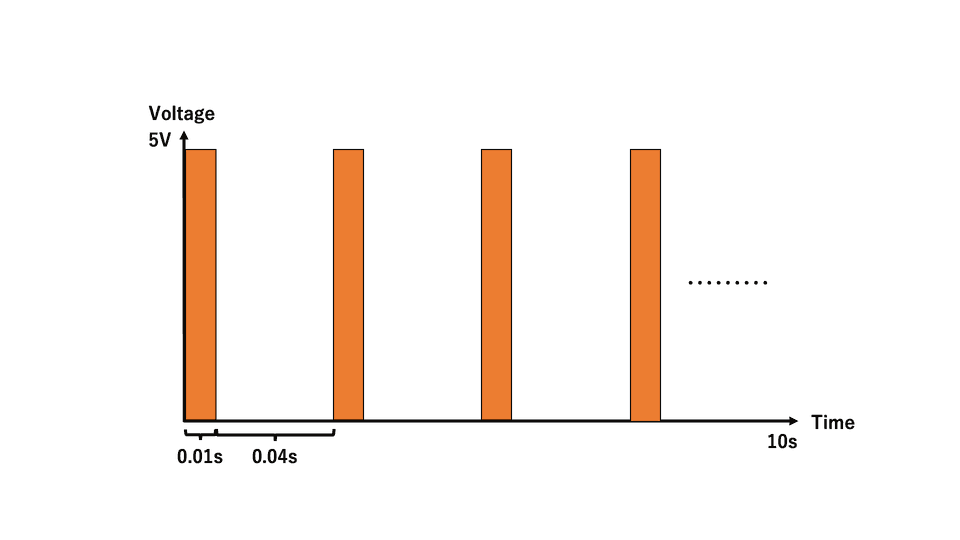
Then, let's repeat the voltage for 10 seconds, alternately moving and releasing the voltage for 1 second. In conclusion, it is the same as when a voltage of 5V was applied for 5 seconds. Therefore, the total number of revolutions is 50.

This time, let's repeat it for 10 seconds alternately for 0.01 seconds. This is also the same as in the example above when a voltage of 5V was applied for 5 seconds. It is also equivalent to hanging a voltage of 2.5V for 10 seconds. In this case, 5V - 10s becomes 2.5V - 10s, so DC motors have the effect of halving the rotational speed.

In this way, if the ratio of the time for applying the 5V voltage to the time for applying the voltage of 0V is 1:1, an average voltage of 2.5V can be applied. Therefore, if this ratio is properly adjusted, various voltages can be given.
For example, if the ratio of a voltage of 5V to a voltage of 0V is 1:4, it can have the same effect as a voltage of 1V on average. If the voltage is applied and released at a long interval, it will break and rotate, but because the interval between them is very short, it seems to return at a constant speed.

Servo Motor control through PWM
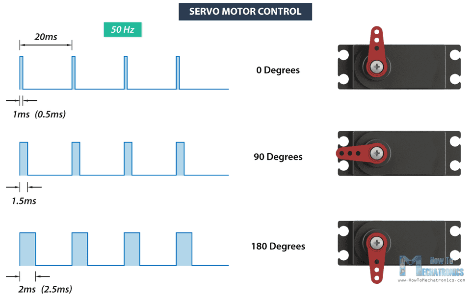
Usually, PWM is used to control a servo motor that can rotate up to 180°, but unlike the DC motor described above, the servo motor has a fixed frequency. In order to control the servo motor, a signal having a 50Hz frequency must be input. That is, it has a time of 20ms per cycle by T = 1/f. In summary, the rotation angle of the servo motor varies according to the width(= duration) of the HIGH signal within a period of 20ms.
Although it depends on the type of servo motor, it usually has an angle of 0° at 1.0ms, 90° at 1.5ms, and 180° at 2.0ms. Details are shown in the data sheet of the servo motor. Exactly 1.5ms is the center, and if it is less than 1.5ms, it moves counterclockwise, and if it is greater than 1.5ms, it moves clockwise.
The servo motor consists of three types: GND(-), VCC(+), and SIGNAL(PWM), and when the following signal is input to SIGNAL, the motor moves at the corresponding angle.

Since the servo motor aims to move to a specific location, it is necessary to continue to emit the above constant signal in order to maintain the location. Otherwise, the motor cannot maintain the angle and turns strangely.
Edit this page on GitHub