DEVHEE/ai-robot-hand-with-raspberry-pi
Robot / AI Robot Hand with Raspberry Pi - 3. Hardware Research
Robot / AI Robot Hand with Raspberry Pi - 3. Hardware Research
Circuit Design
Circuit Diagram
The overall hardware and circuit planning is as follows.

It consists of 14 servomotors that function as each joint, PWM/Servo I2C Interface that can control these motors at once, and Raspberry Pi that serves as the backbone. Breadboard is later constructed together to increase scalability.
Overview of the circuitry

PWM/Servo I2C Interface configuration
First, the PWM/Servo I2C Interface unit will be described. I will call it PWM/servo module for a short.

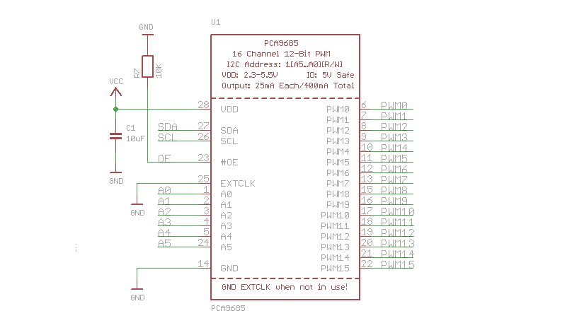
The PWM/servo module to be used is Adafruit's PCA8685 model. The pre-run PWM output of 16 channels may be controlled. Looking at Pinouts, Power Pins have GND, VCC, and V+, and Control Pins have SCL, SDA, and OE. Output ports have 16 ports, and each port consists of V+, GND, and PWM.

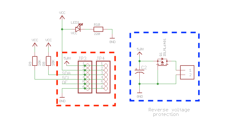
The first thing to note here is the lateral terminal and power.

The red dotted line is a terminal part directly connected to the Raspberry Pi, and from No. 1 to No. 5, it consists of 5.0V(V+), VCC, SDA, SCL, OE, and GND, respectively. 5.0V(V+) supplies a voltage for rotating the motor, and can supply a voltage instead of 5.0V(V+) through 5-6VDC power of a blue dotted line. The VCC supplies power for PWM to the substrate through a voltage of 2.3 - 5.5V. SDA and SCL are used for I2C communication, OE enables output, and GND means ground.

Here, the parts we will use are VCC, SCL, SDA, and GND. Data may be transmitted from the Raspberry Pi to the PWM/servo module through these four terminals.
Raspberry Pi Configuration
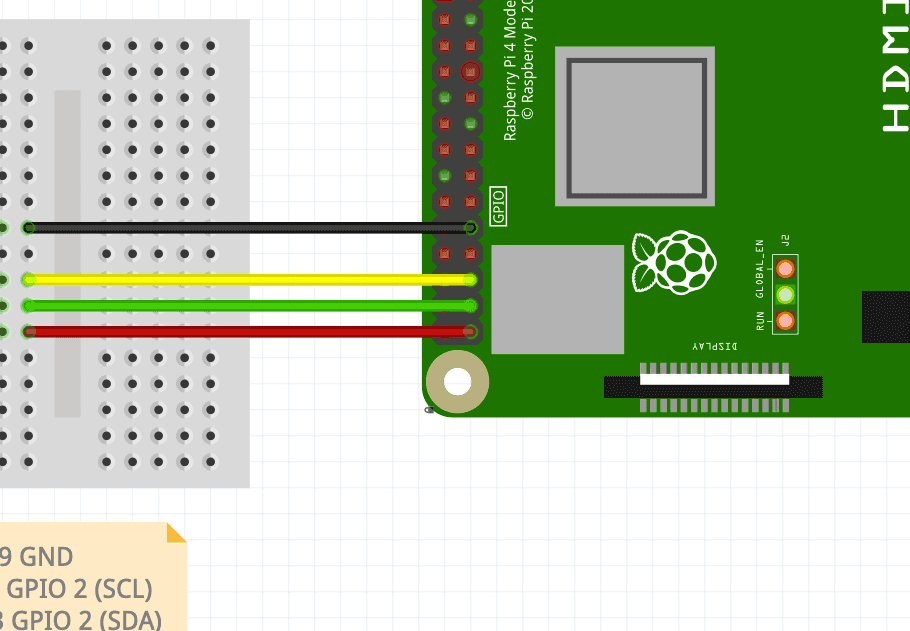
The GPIO of the Raspberry Pi 4B shares a 40-pin header.

Control is possible by connecting this GPIO and PWM/servo module.

The black wire is Ground of pin #9, the yellow wire is GPIO 3 (SCL) of pin #5, the green wire is GPIO 2 (SDA) of pin #3, and the red wire is 3V3 power of pin #1. Each terminal is connected to GND, SCL, SDA, and GND of the PWM/servo module.
One question that can be raised here is why it was connected to 3V3 power rather than 5V power. In fact, it does not matter if it is connected to 5V. The reason is usually explained that if a voltage of 5V is continuously applied to the GPIO, there is a risk of circuit burn. The voltage of 5V entering the Raspberry Pi is forced to 3.3V and emitted.
PWM/Servo I2C Interface signal data control
In summary, the motor power of the PWM/servo module is supplied through an external 5V, the 5V input to Raspberry Pi is adjusted to 3.3V, I2C communication between Raspberry Pi ー PWM/servo module ー Servo motor is performed using lines SCL and SDA.
The servo motor may be controlled by connecting the servo motor to the PWM output port of the PWM/servo module.

The PWM output port consists of PWM', V+, and GND. V+ is shared with the external 5V input of the PWM/servo module mentioned above, and signals of PWM are transmitted through Raspberry Pi and SCL and SDA lines of the PWM/servo module.
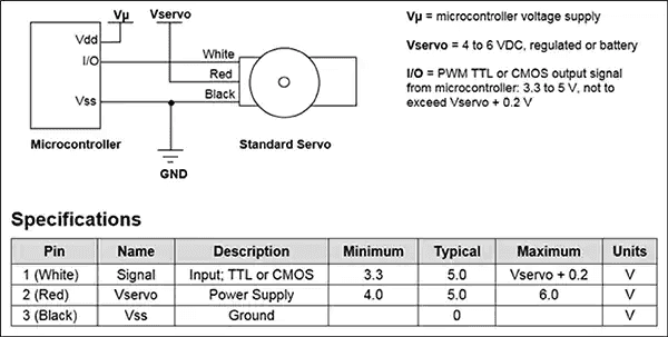
One important point here is Datasheet information of the servo motor connected to the PWM output port. The PWM/servo module PCA8685 looks at the official document, The PCA9685 operates with a supply voltage range of 2.3 V to 5.5 V and the inputs and outputs are 5.5 V tolerant., which satisfies the input of VCC, so the input of 2.3 - 5.5V The servo motor connecting here also has input conditions like this, and the Datasheet of the general-purpose servo motor is as follows.

Pin #1 Signal is a part that serves as PWM, with a minimum input of 3.3V and a maximum input of Vservo + 0.2V. This input is not a voltage for rotating the servo motor, but a voltage for transmitting data to the servo motor (=voltage for operating the servo module), and satisfies the minimum input condition as a voltage of 3.3V is supplied through 3V3 of Raspberry Pi. Pin #2 Vservo, which is a voltage for operating the servo motor, also satisfies Type 5.0V through an external input, and all circuits operate normally.